


Type and Construction
The composite blind flanges are in accordance with manufacturer’s specification. The range of sizes covered is ½ in./16 mm to 36 in./914 mm Class 150. Drilling and outside diameter dimensions of flange sizes ½ in./16 mm-24 in./610 mm are in accordance with ANSI B16.5 and BS 1560, whereas the larger sizes, 28 in./711 mm -36 in./914 mm are in accordance with MSS SP-44. The blind flanges are suitable for use both 16 and 20 bar systems.
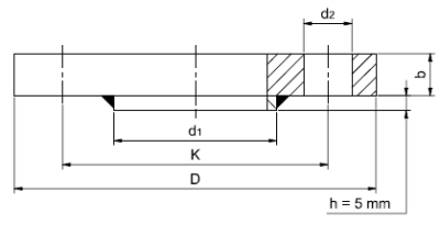
The composite blind flanges are manufactured from forged carbon steel in accordance with ASTM A105 cladded with copper nickel disk. In contrast to raised face blind flanges in accordance to ANSI B16.5, the supplied composite flanges are considered as flat face, since the diameter of the copper nickel disk d1 is equivalent to the flange diameter d4 weld neck stub end in accordance with EEMUA 234, Section 1A. By these means, uniform contact over the weld neck stub end faces is ensured. The recommended bolting is in accordance with ASTM A193-B7. Unless otherwise specified the flanges are protected by hot dipped galvanising. Additional organic coatings such as polyamide epoxy are available on request. Solid blind flanges are available on request.
Tolerances
Tolerances are equivalent to the dimensions for weld neck backing flanges based on EEMUA – 234, Section 1B, Table 1.5.2.
Nom. | Spec. | Flange |
| Diameter of Bolt Holes | Flange | Diameter of | No. Of | Approx. | |
Size | Size | Diameter | K | d2 | Thickness | Disk | Bolt | Total Weight | |
in | mm | D mm | mm | in | mm | b min mm | d1 mm | Holes | (kg) |
½ | 16 | 89 | 60.3 | 5/8 | 15.9 | 14 | 40 | 4 | 0.82 |
¾ | 25 | 98 | 69.8 | 5/8 | 15.9 | 14 | 50 | 4 | 1.04 |
1 | 30 | 108 | 79.4 | 5/8 | 15.9 | 14 | 50 | 4 | 1.31 |
1¼ | 38 | 117 | 88.9 | 5/8 | 15.9 | 14 | 70 | 4 | 1.58 |
1½ | 44.5 | 127 | 98.4 | 5/8 | 15.9 | 14 | 80 | 4 | 1.90 |
2 | 57 | 152 | 120.6 | 3/4 | 19.0 | 18 | 99 | 4 | 3.01 |
2½ | 76.1 | 178 | 139.7 | 3/4 | 19.0 | 18 | 120 | 4 | 4.68 |
3 | 88.9 | 190 | 152.4 | 3/4 | 19.0 | 19 | 130 | 4 | 5.70 |
4 | 108 | 229 | 190.5 | 3/4 | 19.0 | 24 | 158 | 8 | 8.67 |
6 | 159 | 279 | 241.3 | 7/8 | 22.2 | 27 | 212 | 8 | 15.46 |
8 | 219.1 | 343 | 298.4 | 7/8 | 22.2 | 31 | 270 | 8 | 24.90 |
10 | 267 | 406 | 362.0 | 1 | 25.4 | 38 | 320 | 12 | 41.23 |
12 | 323.9 | 483 | 431.8 | 1 | 25.4 | 41 | 370 | 12 | 70.55 |
14 | 368 | 533 | 476.2 | 1 1/8 | 28.6 | 45 | 430 | 12 | 93.16 |
16 | 419 | 597 | 539.8 | 1 1/8 | 28.6 | 51 | 482 | 16 | 123.99 |
18 | 457.2 | 635 | 577.8 | 1 1/4 | 31.8 | 52 | 530 | 16 | 147.55 |
20 | 508 | 698 | 635.0 | 1 1/4 | 31.8 | 58 | 585 | 20 | 191.00 |
24 | 610 | 813 | 749.3 | 1 3/8 | 34.9 | 71 | 685 | 20 | 285.74 |
28 | 711 | 927 | 864.0 | 1 3/8 | 34.9 | 81 | 800 | 28 | 434.66 |
32 | 813 | 1060 | 978.0 | 1 5/8 | 41.1 | 95 | 905 | 28 | 665.63 |
36 | 914 | 1168 | 1086.0 | 1 5/8 | 41.1 | 105 | 1000 | 32 | 886.43 |